11 Steps to Follow to Get Your Design Ready for Production
.jpeg)
1. Avoid extremely thin walls or parts in your design
The quality of the milling work is determined by the stiffness of the part. The thinner the material, the more vibrations are created during milling. These vibrations can make the part less accurate. For corpuses, the standard minimum thickness for back walls is 12 millimeters. The standard for the other parts (walls and shelves) is 18 millimeters. Before you start drawing, always look up the standard thicknesses of the type of wood so that you apply this to your design.
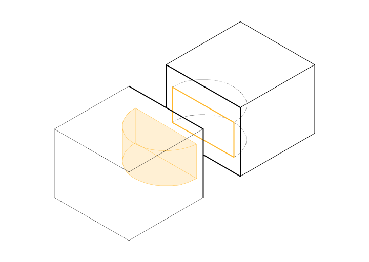
2. Avoid parts that cannot be CNC-milled at all.
Unfortunately, not all possible shapes can be made by a CNC router. This makes the design more difficult or sometimes impossible to produce. An example of this is "bent holes" or holes in the middle of a part (the router has to enter the design somewhere). You can better split your design in two parts then to get the preferred cut-outs (see image).
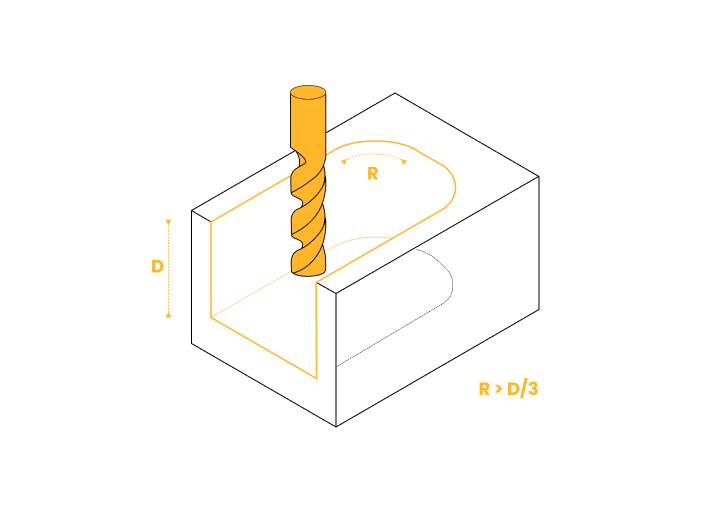
3. Design cavities based on rules of thumb about depth-to-width ratios
You can improve your design by smartly considering rules of thumb about the depth to width ratio of cavities and holes. Cavities that are too deep can result in deflection and breakage of the cutter. It can also lead to blockages when disposing of the sawdust. Cavities should preferably have a maximum depth of four times the width of the cavity. For example, a cavity width of 15 mm should not exceed 60 millimeters in depth. You can read more about it in this help center article.
4. Take curves of internal corners into account
Milling internal edges and corners can be demanding on the tool. Since most cutters are cylindrical and cannot make sharp internal edges, it is important to add radii to internal edges in your design. This prevents unnecessary tool wear, time and money. It is a good rule of thumb to include in your design a radius of at least 130% of the radius of the cutter. So if the cutter has a radius of 5mm, design the internal corner with a radius of at least 6.5mm. This prevents unnecessary wear and increases speed. For CNC woodworking, the minimum possible radius is 2 millimeters.
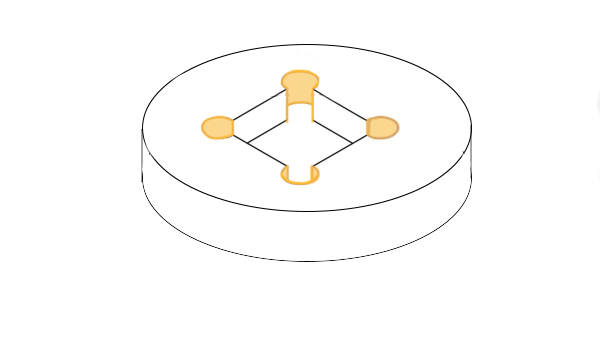
5. Add 'dogbones' to make parts fit together better
Because internal corners are always round and never straight, sheet material with straight corners that needs to fit or slide precisely into them may not fit. The straight corner will bump into the rounding of the internal corner. You can solve this by working with 'dogbones' (see image).
6. Avoid designing cut-outs that are too small
Most CNC machines have a minimum milling diameter of 2 millimeters. Any cut-outs smaller than 2 millimeters need special tools. Machine costs and time increase as a result. Therefore, avoid features and details that are too small except when necessary. In general, it is better to design bigger cut-outs so tools don't need to be switched too often. With a bigger drill bit, more material can be removed at once which again saves production time and costs.
7. Design holes with standard dimensions
Holes with standard dimensions are milled using standard drill dimensions. This saves machine time and costs, as holes not designed to the standard would otherwise require a finger mill. Standard sizes for holes are: 4, 5, 6, 8, 10 or 12 millimeters. For non-standard holes, it is a rule of thumb that the depth should be four times the diameter of the hole.
8. Adhere to standards for doors and shelves.
When drawing a body (for example, for kitchens), it is wise to keep the standards and rules of thumb in mind. Standard dimensions for kitchen corpuses for example are 150, 300, 450, 600, 800 or 900 millimeters in width and 290, 360, 570, 720 or 900 in height. Always allow 3 millimeters space between two doors and make sure that doors close on top of the side panels (not between them). For fixed shelves, no margin needs to be maintained (as wide as the space between the walls). In this case, allow 8 millimeters for the dowels. For loose shelves, the rule of thumb is to leave 1.5 millimeters on both sides. No dowel holes need to be drawn here. When drawing rows of holes for adjustable shelves, keep in mind that the holes are often 4 millimeters in diameter and should be 32 millimeters apart.
9. Stick to standard depths for dowel holes
Often dowels are designed to be overly large and deep. The number of dowels used is also often unnecessarily high. As a rule of thumb, keep in mind that dowels usually do not need to be larger than 8 millimeters in diameter. Generally, they are placed at half the thickness of boards, 50mm from the sides. The depth often does not need to be more than 5 millimeters on either side. Two dowels on either side are usually sufficient to secure a board.
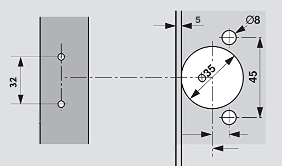
10. Draw your hinges in the right way
A commonly used diameter for a hinge hole for a door is 35 millimeters, 5 millimeters from the edge. Above and below the hinge hole, place two screws of up to 10 mm in diameter to secure the hinge (see illustration). In the side wall, adjacent to the door, the other half of the hinge is attached with two screws of 5 millimeters in diameter, both 37 millimeters from the edge. The distance between these two screw holes must be at least 32 millimeters.
11. Consider adding plinths when drawing cabinets
A plinth placed against adjustable legs is often 100 millimeters high and is usually placed 50 millimeters back from the face of the cabinet. There is often 1.5 millimeters between plinths at the top and cabinet doors. Top plinths are often no higher than 50 millimeters. This also applies to plinths along the sides of your design (for example, towards the wall). Don't forget to include information about the dimensions of the surrounding space and deviating objects in the vicinity such as doors, light switches or elevators.
Conclusion
If you make sure your drawing has taken all the above items in consideration, you will save yourself time and cost in the production process. If you have any questions about how to make a file ready for production, please don't hesitate to reach out to us via chat or email.
Related articles:
How can I get my wooden parts delivered as fast as possible?
A guide to 2D error free files
Upload your design file and get a quote
within days
Quality production with trusted production network.

%20(1).webp)
.webp)


.webp)